製品
 オックスフォード・インストゥルメンツー事業部ページ

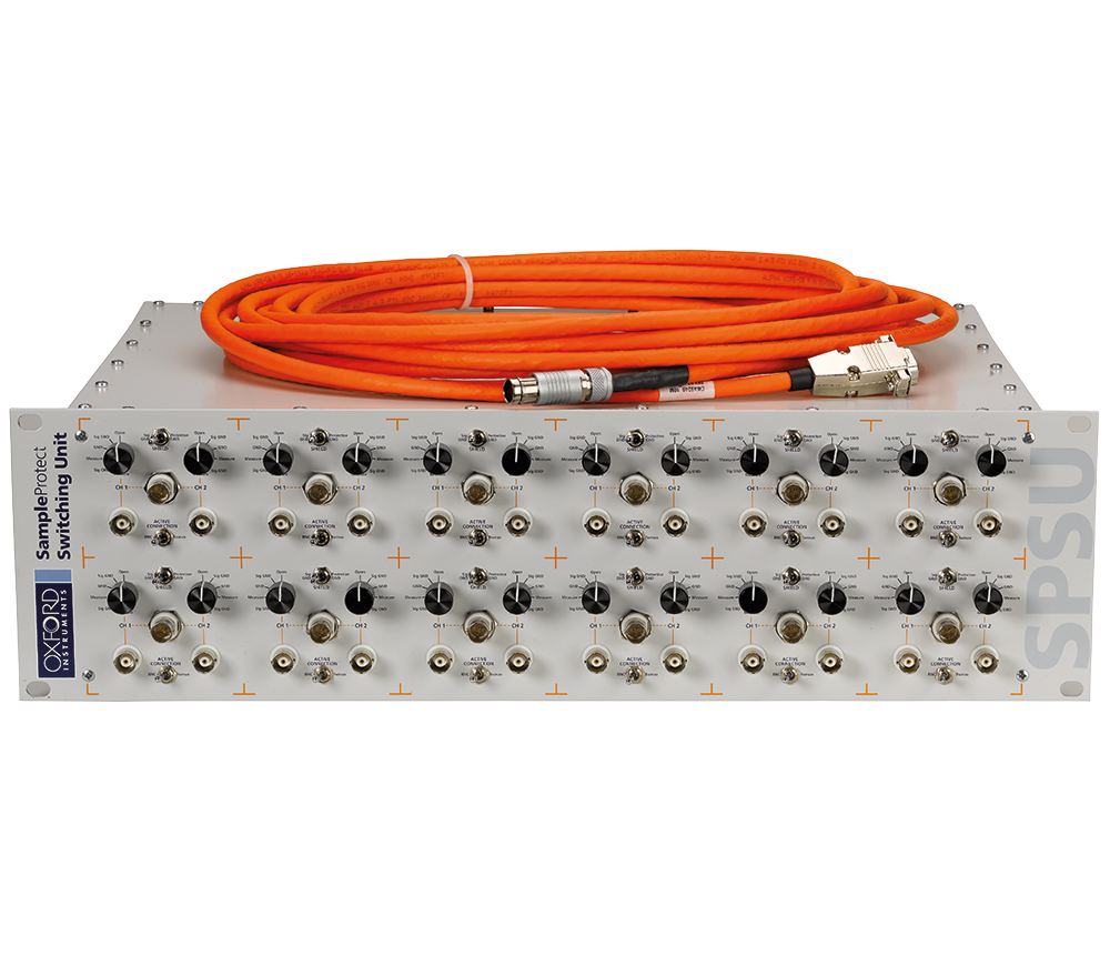
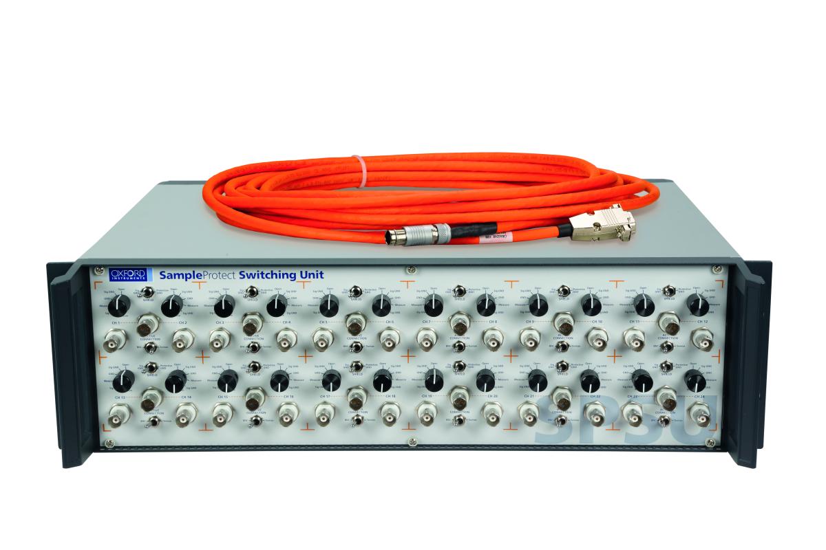
SampleProtect は、敏感な試料を偶発的な静電気放電(ESD)から保護するための徹底した方法を、実験を行う方々に提供することをコンセプトとしています。このシステムは、測定用グレードのケーブルと試料プローブを介して、等電位プラグ用の追加ソケットを含む試料ホルダーとリンクされたラックマウント式の SampleProtectスイッチングユニット(SPSU)で構成されています。
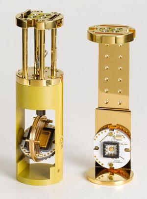
試料ホルダーはプローブから取り外すことができ、各プローブは複数のタイプの試料ホルダーを収容できます。また、試料ホルダーはプローブ間で、あるいはHelioxVTまたはKelvinoxJT ULTインサートにも移すことが可能です。
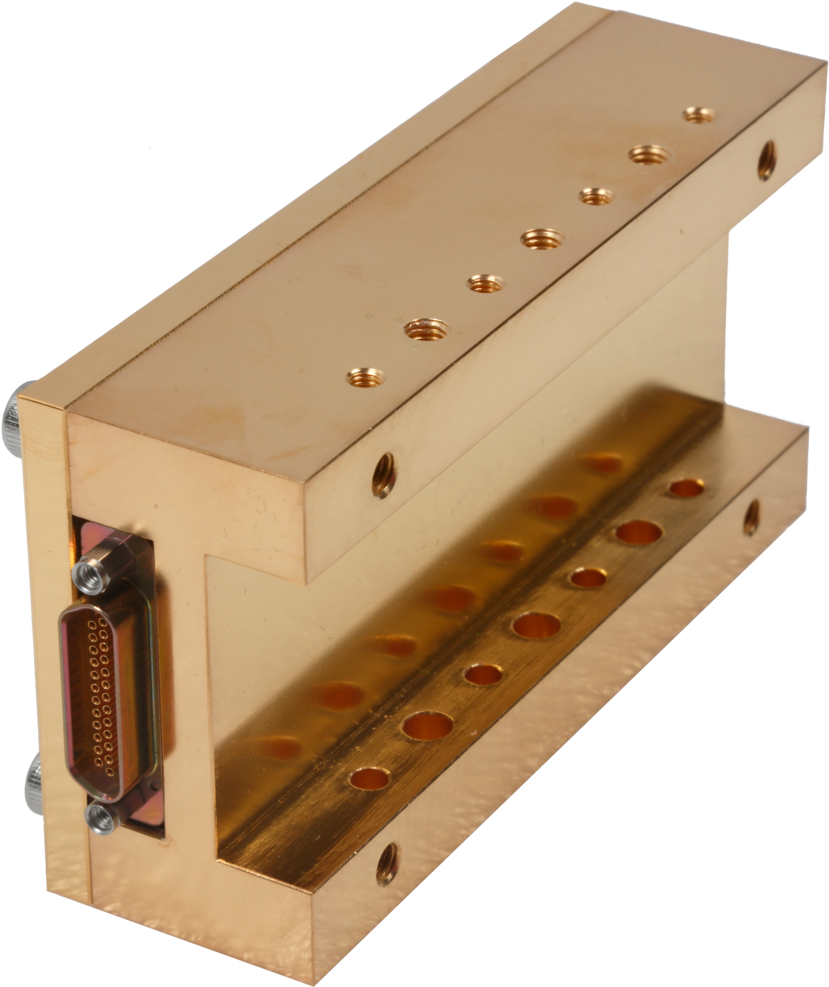
シールドされた測定ケーブルに加えて、100mK以下までの極低温で取り付けることができる多段ローパスフィルタがあります。このフィルタは、4つの異なるカットオフ周波数のフィルタオプションがあり、24本の信号線をフィルタする機能があります。また、フィルタPCBのシールドおよび排熱のため、RFガスケットを備えたAuメッキのCuシャーシで構成されています。フィルタ部品は慎重に選択された表面実装部品で、周囲温度から100mK以下の温度範囲で非常に優れた安定性を実現することができます。
サンプルをサンプルホルダーに装着する際、ESDプラグを挿入します。 このプラグは、サンプルへのすべての電気的接続をつなぎ、ESDによってサンプルに有害な電圧が発生しないようにします。 このプラグは、サンプルホルダーとサンプルの輸送中も固定されているため、サンプルをサンプルを調整する実験室から測定する実験室へ、あるいは共同研究者のラボへ安全に輸送することができ、ESDによるダメージから保護されます。
サンプルホルダーをプローブに装着する際、ユーザーはESDプラグを所定の位置に固定します。 次に、プローブをSPSUを介して目的の測定機器に接続します。 SPSUのスイッチを設定し、すべての信号線を保護グラウンドまたは測定器グラウンドのいずれか希望のグラウンドに接地します。 スイッチが正しく設定されたら、ESDプラグをサンプルホルダーから取り外します。 サンプルに問題がなければ、測定チェックを行い、サンプルが接続されていること、信号線が機能していることを確認します。 その後、プローブをクライオスタットにセットし、必要な温度まで冷却します。
サンプルとプローブがクライオスタットに挿入され、測定が開始されると、SPSUをブレークアウトボックスとして使用し、実験中に信号線の切り替えや監視を行うことができます。
測定ケーブルは、26(19/38)AWGの錫メッキ銅10ペアと22(19/34)AWGの錫メッキ銅3ペアの計13ペアを撚った細心の注意を払ったケーブルです。各ペアは、ホイルスクリーンで個別にスクリーニングされています。それぞれのスクリーニングには、他のすべてのスクリーニングから隔離するための外部絶縁とドレインワイヤーが備えてあります。
さらに、ケーブルには、内部絶縁と外部スクリーニングブレードを持つ全体ホイルスクリーニングがあります。全体スクリーニングにもドレインワイヤーがあります。この構造は、外側のスクリーニングを保護グランドに接続して全体的なスクリーニングを容易にしますが、さらに、任意のペアをそのチャネルの特定の測定グランドにスクリーニングすることができます。 クロストークは周波数の上昇とともに増加することが、仕様にも示されています。
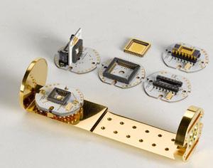
PCBとLCCホルダーは、熱伝導率を最適化するためにセラミックの窒化アルミニウム(AlN)製です。
電気接点のメッキはNiフリーで、サンプル領域での残留電界効果を最小限に抑えています。
以下のサンプルホルダーを用意しています:
PCBサンプルホルダーインターフェース - サンプルホルダーPCBに接続するための44本の非磁性スプリングロードピン
TeslatronPT と互換性のある3つの標準プローブ
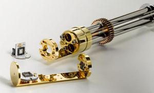
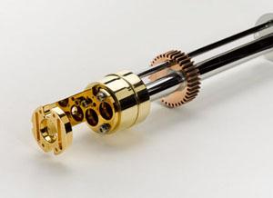
各プローブは、サンプルインガス(SIG)またはサンプルインバキューム(SIV)のバリエーションがあります。 プローブのシャーシは、3本の薄肉ステンレスチューブで構成されており、剛性が高く、直線的で、熱伝導率の低い構造となっています。また、電気的に分離した空間を作り、測定ロームを診断配線や駆動用配線からシールドしておくことができます。
| 項目 | 値 |
| 温度範囲 | -40 ~ 80°C |
| 定格電圧 | 300VRMS |
| 推奨周波数範囲 | DC – 100kHz |
| 相互容量 | 38pF @ 1kHz |
| 自己インダクタンス | <0.30µH |
| 導体DC線抵抗 | <0.18Ω @ 20°C |
| シールドDC線抵抗 | <0.12Ω @ 20°C |
| 項目 | 値 | 値 |
| 26AWG ペア | 26AWG ペア | 22AWG ペア |
| ツイスト回数 | 12 /ft (最小) | 12 /ft (最小) |
| 温度範囲 | -40 ~ 80°C | -40 ~ 80°C |
| 定格電圧 | 300VRMS | 300VRMS |
| 相互容量 | 30pF/ft @ 1kHz | 38pF/ft @ 1kHz |
| 対地静電容量 | 54pF/ft @ 1kHz | 68pF/ft @ 1kHz |
| 特性インピーダンス | 55Ω | 43Ω |
| ラインインダクタンス | 0.18µH/ft | 0.16µH/ft |
| 導体DC線抵抗 | 38Ω / 1000ft @ 20°C | 15.5Ω / 1000ft @ 20°C |
| シールドDC線抵抗 | 34Ω / 1000ft @ 20°C | 14.5Ω / 1000ft @ 20°C |
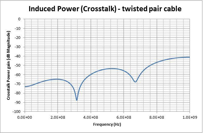
チャンネル1の励磁駆動電流によりチャンネル2に誘起されるクロストーク信号を周波数の関数としてプロットしたもの:
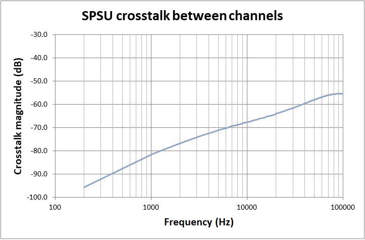
同じケーブル構造の別のツイストペアの導体に励磁駆動電流を流した結果、ツイストペアの一方の導体に誘導されるクロストーク信号を周波数の関数としてプロットしたもの。 各ペアはシールドされ、シールドは機器のグランドに接地されています:
クロストークの測定は、180cmのケーブル長で測定したものです。クロストークは、周波数が高くなるとともに増加します。
クロストークの測定は、180cmのケーブル長で測定したものです。クロストークは、周波数が高くなるとともに増加します。
| 項目 | 値 | 値 | 値 | 値 |
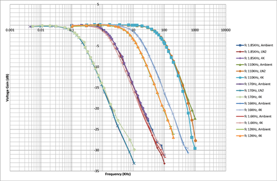
| カットオフ周波数 | 170Hz | 1.85kHz | 12kHz | 110kHz |
| 通過帯域 | 85Hz | 900Hz | 5KHz | 40kHz |
| 通過帯域における挿入損失 | <0.6dB | <0.6dB | <1.0dB | <1.0dB |
| 周波数除去 | -45dB @ 100kHz | -33dB @ 100kHz | -36dB @ 1MHz | -24dB @ 1MHz |
フィルターの周波数特性のボードプロットは、異なるカットオフ周波数の構成を示します:

© オックスフォード・インストゥルメンツ 2025